|
|
I ask you to look both ways. For the road to a knowledge of the stars leads
through the atom; |
The Vincent-Midgley precession technique is a powerful method for improving the quality of electron diffraction data from bulk crystals (Vincent and Midgley, 1994). Direct methods are a family of phase recovery algorithms that can restore the structure from diffraction intensities alone. In order for them to work reliably, however, high quality intensities are required. Usually, intensities in bulk structure studies are acquired using X-ray diffraction, a method that reliably offers high quality datasets (kinematical diffraction).
Transmission electron diffraction offers some advantages over x-ray methods, primarily that the scattering is stronger (also a disadvantage), and that one can use it to study very small crystals. However, the quality of intensities from bulk electron diffraction is usually too poor to solve atomic structures reliably due to multiple scattering (dynamical diffraction). In the precession electron diffraction (PED) technique, the beam is deflected prior to interaction with the specimen to form a tilted illumination condition. After interaction with the sample, the diffracted beams are deflected using a complementary deflection (de-scan). Applying this tilt/de-tilt serially forms a hollow cone of illumination at the image plane and a diffraction pattern at the back focal plane, seen in the figure below.
This scheme is equivalent to rocking the crystal as is done in the Buerger x-ray precession method. However, the result is quite different since the small dimensions of the crystal give rise to an elongated shape function in reciprocal space (the reciprocal lattice rods, or relrods), and the scattered intensity has been modified from the kinematical sinc function depending upon the number of simultaneously excited beams and the thickness of the specimen. In reciprocal space, the Ewald sphere is swept through the relrods within a finite range of excitation errors sg defined by the constraints imposed by precession angle f and incident electron wavelength. The collected intensity is thus an integral of the scattered intensity within that range of excitation errors. The following figure shows one snapshot of the integration. In a), the reflection g is intersected by the Ewald sphere with positive excitation error. The beam may have an angular spread of a, denoted by the solid curve. The dimension 2R0 describes the zeroth order Laue zone (ZOLZ), where half that dimension is the radius of the ZOLZ. Reflections in the middle of the 'bowl' are weakly excited, and reflections close to the edges of the bowl intersecting the x-y plane are strongly excited. In b), a cross-section of the bowl at the x-y plane is shown demonstrating how the zeroth order Laue zone precesses about the z-axis. A complete precession occurs when q traverses 2p.
Click here for an animation of precession in action (requires Microsoft Powerpoint 2002 or higher).
Some of the interesting features inherent to precession:
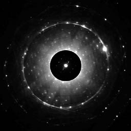
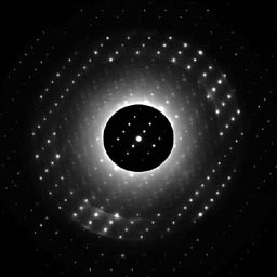
We have built two precession systems for conducting PED experiments. One was retrofitted on a Hitachi H-9000 UHV microscope and the other was installed on a JEOL 2000FX and later moved to a JEOL 3000F. Some experimental images are shown below demonstrating the effects of the precession technique. They are diffraction patterns from a very thick Mg3V2O8 crystal. They have been taken under identical environmental conditions, processed in the same bath, scanned under the same conditions, and processed identically in Photoshop. A very moderate precession angle (~ 5 mrad) was used to form the right-hand pattern to demonstrate the effects of precession. The extension by precession of the first order Laue ring into an annulus of width 10 mrad is clearly seen, as well as the blending of non-systematic dynamical effects into a radially diffuse background. This dynamical background averaging can improve intensity measurements by considerably simplifying the problem of background subtraction. One can also see that the reflections in the ZOLZ are more clearly defined. It is also apparent that dynamical scattering still contributes to the image, so thin specimens are preferred, however correction factors can be applied if the specimen is thick if some of the structure factors are known.
The quality of the intensities is readily apparent in experimental patterns. The figure below shows the kinematical amplitudes compared to precession intensities for the (Ga,In)2SnO4 M6 phase, a transparent conducting oxide materials system. The intensity ordering is strikingly similar. Intensities are used because this specimen is somewhat thick: in the limit of large thickness, the square of the precession amplitude more closely approximates the true amplitude. The primary deviations occur in the reflections near the central beam and decay as the excited beams in the Ewald circle in the x-y plane curve away from the systematic excitation condition. We have studied this carefully using multislice simulation and have ascertained that it occurs consistently due to systematic diffraction paths being excited near the transmitted beam. It diminishes with larger precession cone semi-angle and smaller specimen thickness. Fortuitously, these reflections have little bearing on the structure (they represent low spatial frequencies) and additionally, their phases are easiest to recover via imaging. In a priori structure investigations, one can exclude these reflections to get better results from direct methods, and if used in conjunction with high-resolution imaging, the phases are known and can be used to define phases of other reflections which have unknown phase.
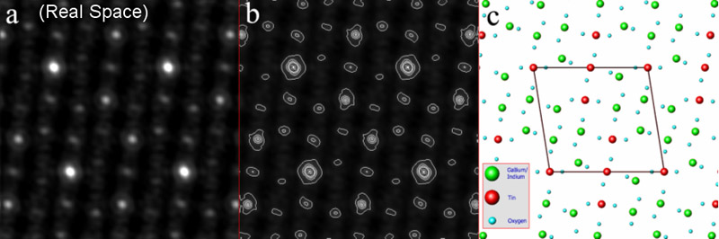
A scattering potential solution map generated from the precession intensities (pattern b above) is shown below in map a with the corresponding contour map in b. The structure in c below shows the known structure ascertained via HRTEM, electron diffraction, X-ray diffraction, and refinement using neutron diffraction (Sinkler, et al 1998). The cation positions are clearly resolved in the precession-derived map and come on average within 4 pm of the refined structure positions. The R-factor for the experimental precession intensities is very low: for unrefined intensities compared to multislice simulations, the R1 is 0.118, compared to > 0.4 for the non-precessed data. This further demonstrates the quality of the precession intensities.
We have investigated a number of other materials systems and have looked at the correction factors in detail to understand how they work and to explore if they can be used without any previous knowledge of the structure. Methods for a priori structure investigations have been proposed based on this work. Please see C.S. Own's thesis for more details, in particular chapter 4.